 |
Department of Physics | AstroLab |
Plate Scale and Focal Lengths: A Tutorial and Worked Example
Plate scale relates the angular field of view of a frame, d(theta), (typically measured in arcseconds), to the size of the detector, ds, either in terms of a physical dimension (typically millimetres) or per pixel. Whilst a useful quantity in its own right - since knowledge of the plate scale tells you the field of view for a given detector - the plate scale also gives you the total length of the focal path, f, via:
d(theta) / ds = 1 / f
It is necessary in several Astrolab projects to be able to determine the plate scale of the telescope-CCD combination, and the focal length of the telescope. Whilst the details of the various current telescope-CCD combinations are outlined on the Astrometrica tutorial page here, you may find that your project requires you, for example, to perform astrometry on an archived image that was taken when the telescope-CCD combination was different - perhaps because the CCD has been upgraded or a motorised focusser has been added to the telescope. We'll therefore describe the theory of how to extract these parameters from an archived image and go through a worked example.
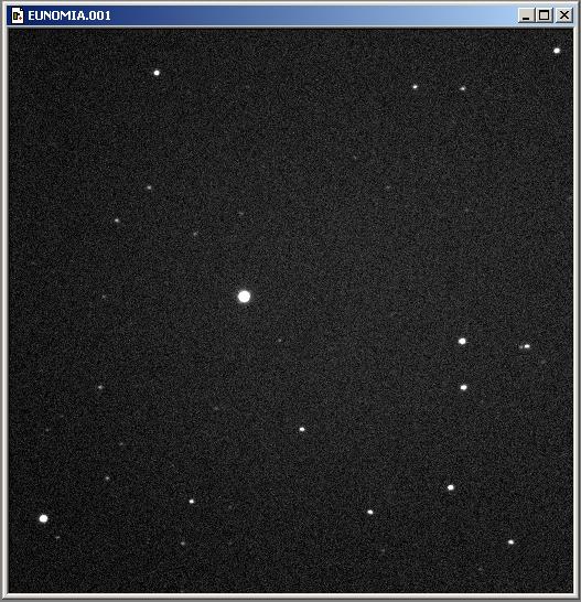
To find the plate scale for a particular image you'll need at least two well defined reference targets within the frame; if the frame you have doesn't allow you to accurately locate (in RA and Dec) two such targets, you may wish to calculate the plate scale using an observation from a similar date (for which you can be confident that the telescope-CCD combination is the same), and then apply your derived results in your astrometry of the original image. For our tutorial, we'll use an old image of the asteroid (15) Eunomia, taken from the second 10" telescope back in 2002 (E:\\10_2\2002\02_11_10\EUNOMIA.001)
It is essential that you do not use a moving target in your frame, such as an asteroid or comet, as a reference target! The error on their RA and Dec will be too great to accurately determine their location in RA and Dec at the time of observation. Always use stars.
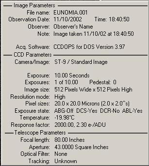
Armed with a suitable image containing at least two references, you'll need to identify each target in order to determine their RA and Dec. Open the image with CCDOPS and click on Display > Parameters to find the time and date of the observation, which is automatically stamped into the image's file header by the CCD. In our example here, the observation date is 11/10/2002 (remember that the date format is the US standard MM/DD/YYYY, so this image is from the 10th November 2002), and the time of observation is 18:35. Also note down the image size (x pixels by y pixels) and the pixel size (x microns by y microns), as these will help to to identify the CCD model used for the imaging - we'll need this info later. Here we can see the image is 512x512 pixels in size.
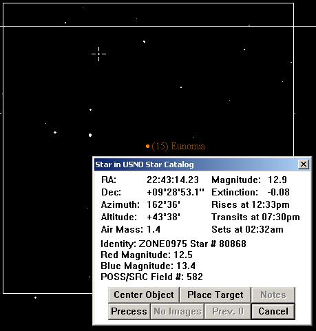
Now open Earth Centred Universe and set the time and date to match those of the observation. Next, search for the primary target and centre the view on it - you may find the Center menu useful for this. Then left-click the primary target of the frame (i.e. what the image is of, not the first reference target); this will bring up the target info menu, and click the place target button, which should enclose the target with a box whose size reflects the field of view of the image, allowing you to determine which reference stars can be used. Find at least two stars in the field of view that you can see in the image, and left-click them to view their RA and Dec coordinates. Note these values down. If you can use more than 2 reference stars, do so - it will (in principle) reduce the error on your plate scale measurement, and offers a sanity check if the numbers don't all agree! If you have difficulty matching stars in the image with the Earth Centred Universe view, try rotating the image through 180 degrees in CCDOPS (Utilities > Flip/Rotate Utilities)- remember that the CCD might be upside down on the telescope! This is in fact the case for our example here.
Return to CCDOPS and find the x-y pixel coordinates of the reference centroids. This can be done accurately using the crosshair tool - you'll find a show/hide toggle for the crosshair tool under the Display menu. The position of the crosshair can be fine-tuned with the arrow keys, allowing you to place the crosshairs over the centre of the magnified image.
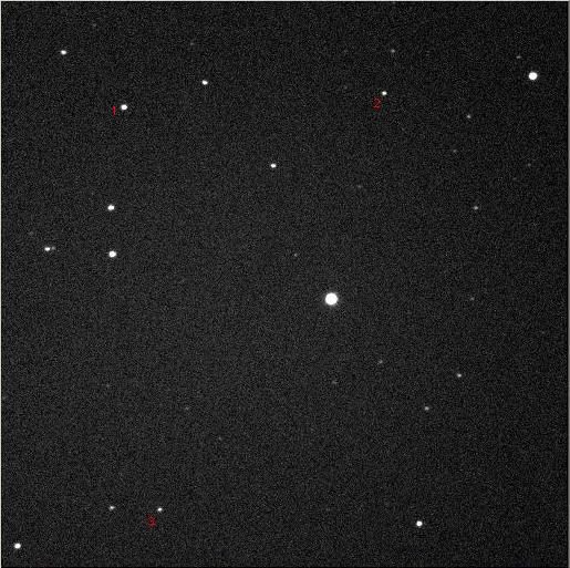
From our example, we'll identify the following reference stars:
Star1:
RA of 22:43:06.11 at x = 112
Dec of 09deg 25'08.7" at y = 96
Star2:
RA of 22:42:50.18 at x = 347
Dec of 09deg 28' 05.7" at y = 84
Star3:
RA of 22:43:11.46 at x = 144
Dec of 09deg 19' 44.2" at y = 459
With the RA and Dec coordinates for at least two targets, you can find the distance between the two in terms of angle - generally, you'll want this angle in arcseconds which means that we must convert the difference in RA from the usual units of "time" into arcseconds, using this formula:
RA difference [arcsecond] = RA difference [seconds of time] x 15 cos(Dec)
It may be confusing to think that the conversion is dependent upon the declination; it may be useful to consider that at the poles, all 24 hours of RA are located at a single point on the sky, so the conversion is meaningless - effectively, RA tends to 0. At the equator, we recover the standard relationship of there being 24 hours of time in 360 degrees of rotation, and hence:360/24 deg/hr = 15deg/hr => 15arcsec/sec
In our example here, we find the following differences (make the second to arcsec conversion using the mean declination of the two targets):Star1 - Star2:
delta_RA(secs) = 24.05 at a mean dec ~ 9.5 deg ==> delta_RA(arcsec) = 355.8
delta_Dec(arcsec) = 12.6
Star1 - Star3:
delta_RA(secs) = 2.77 at a mean dec ~ 9.4 deg ==> delta_RA(arcsec) = 40.9
delta_Dec(arcsec) = 548.9
Star2 - Star3:
delta_RA(secs) = 21.28 at a mean dec ~ 9.4 deg ==> delta_RA(arcsec) = 314.9
delta_Dec(arcsec) = 561.5
So with differences in x and y in terms of arcseconds, find the angular separation of the targets in the usual manner:
r (arcsecs) = sqrt[ ( RA_2(arcsec)-RA_1(arcsec) )**2 + ( Dec_2(arcsec)-Dec_1(arcsec) )**2 ]
Hence, in our example:Star1 - Star2:
R = 356 arcsecs
Star1 - Star3:
R = 550 arcsecs
Star2 - Star3:
R = 644 arcsecs
In the same fashion, find the number of pixels separating the targets:
r (pixels) = sqrt[ ( x_2(pixels)-x_1(pixels) )**2 + ( y_2(pixels)-y_1(pixels) )**2 ]
For our example:Star1 - Star2:
#pix = 235.3 pixels ==> d(theta)/ds = 1.51 arcsec / pixel
Star1 - Star3:
#pix = 364.0 pixels ==> d(theta)/ds = 1.51 arcsec / pixel
Star2 - Star3:
#pix = 426.4 pixels ==> d(theta)/ds = 1.51 arcsec / pixel
Obviously, the ratio r(arcsec) / r(pixels) therefore gives you the plate scale in units of arcsec/pixels. To convert this to a plate scale in terms of arcsec/mm, we'll need to know the size of the pixels. To determine this, first find out which CCD was used to capture the image - open the image in CCDOPS and check the Display > Parameters menu to find the image dimensions, and read off the pixel size from the table below:
| CCD | Image Dimensions (pixels) | Pixel Size (microns) |
| ST6 | 375 x 242 | 23 x 27 |
| ST7 (double binning mode) | 382 x 255 | 18 x 18 |
| ST7 (standard binning mode) | 765 x 510 | 9 x 9 |
| ST9 | 512 x 512 | 20 x 20 |
Now convert from pixels to a physical scale by multiplying by the pixel size. There are two important things to remember: 1) the ST6 had rectangular pixels, so be sure to account for this, and 2) pixel sizes are quoted in microns, not millimetres!
Our example frame was taken with an ST9 CCD - recall earlier we noted that the image dimensions were 512x512 pixels. Hence we apply a pixel size of 20 microns to determine a final plate scale of 75.5 arcsec / mm.
Finally, to determine the focal length of the telescope-CCD combination (in millimetres), use the following relationship:
d(theta) / ds(mm) = 206265 / f(mm)
Our example therefore suggests a focal length of 2732mm - c.f. with the current focal length of the 10"(2) telescope at 2915mm, now that a motorised focusser has been added!
R.A.Crain 18/11/2004| Back to the AstroLab Home Page | jrl | 2013-Dec-22 23:33:33 UTC |